Logic Gates
Logic Gates: Overview
This Topic covers sub-topics such as Logic Gates, Truth Table in Logic Gates, Boolean Algebra, Integrated Circuits, The AND Gate, The OR Gate, The NOT Gate, The NAND Gate, The NOR Gate, The XOR Gate and, Formation of XOR Gate Using NOR Gate Only
Important Questions on Logic Gates
The same input signal is applied to both the (input) terminals of a given logic gate.
If the output is the(i) same as the (common) input signal
(ii) inverted with respect to the (common) input signal,
Identify the logic gate/s involved in each case.
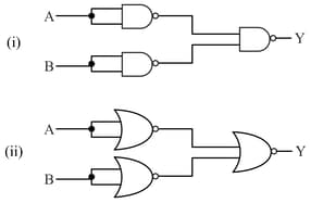
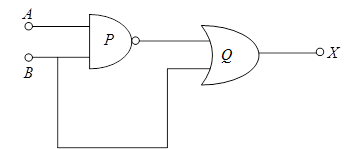
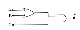
Identify the logic gates marked and in the given logic circuit.
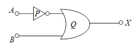
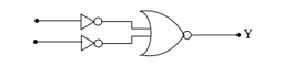
Identify the logic gates marked P and Q in the given logic circuit.
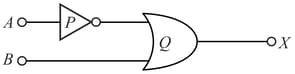
Write down the output at X for the inputs A = 0, B = 0 and A = 1, B = 1.
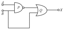
(i) Identify the logic gates marked P and Q in the given logic circuit.
For the following logic circuit, the truth table is:
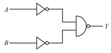
Write the truth table for the given circuit:
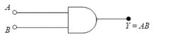
The output of an AND gate is connected to the input of a NOT gate. Draw the logic circuit of this combination of gates and write the truth table.
Give the symbol and truth table of OR gate and AND gate.
Which of the following gates is a universal logic gate?
How many NAND gates are required to form an AND gate?
To get output in given circuit, which of the following input will be correct?
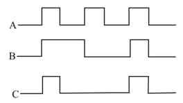
For a logic gate & are input and is output voltage waveform then logic gate is :-

For a logic gate are input and is output voltage waveform then logic gate is :-